06 Jul Remote Loads and Constraints
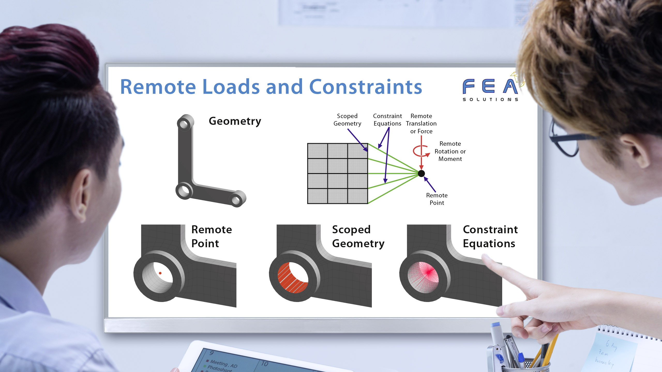
Remote loads and constraints are used to apply boundary conditions to faces of an FEA model (the scoped geometry) from a remote point in space.
Remote loads and constraints are applied in two steps:
1. Adding a nodal load or constraint to a point in space, which can be defined by co-ordinates or by the geometry itself (e.g. the centroid of the chosen geometry).
2. Connecting this point to the nodes on the FEA model. This can be done via the use of massless beam elements or by constraint equations (https://fea-solutions.co.uk/linear-structural-contact/).
These line elements or equations can have their properties defined in different ways:
– Rigid – The scoped geometry cannot deform.
– Deformable – The scoped geometry can deform.
– Coupled – Allows the scoped geometry to have the same degrees of freedom solution on its nodes as the remote point location.
– Beam – This connects the remote load to the model using massless beam elements. If this is chosen the material properties must be defined for this massless beam (apart from density), as do the radii of the beams. This behaviour can also prevent the model from being over-constrained in some cases as it is a more direct than using constraint equations.
For a remote displacement, translations or rotations can be defined.
A remote force is equivalent to a regular force load on a face or edge plus the moment it would generate.
Please call us today on +44 (0)1202 798991 for any engineering analysis requirements you might have.